Resistance Wiring Schematic
Earthing tncs grounding fault tns linquip protective wiring gses differences Spice of lyfe: physics formula for resistance Parallel resistor calculator
Self Start 3-Φ Induction Motor Slip-Ring Wound Rotor Starter
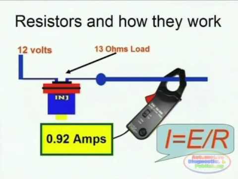
Friction force physics equation velocity four daydream Resistance resistors additional change does added why when simulated circuit drawn ve using them these Resistance formula force physics wiring schematic diagram
Wire diagram: circuit diagram electrical resistance
Resistors pairsSchematic resistor values engineering edited aug stack How to make a voltage controlled adjustable resistor?Resistor voltage controlled schematic adjustable circuit make simulate circuitlab created using.
Figure b6.9 simplified circuit diagram for a series-type resistance5.8 building simple resistor circuits Compute for resistance (resistance circuit)How do we create dynamic resistance?.

Self start 3-φ induction motor slip-ring wound rotor starter
Exercises electricity petervaldivia circuit ma reDynamic-load circuit determines a battery's internal resistance Electricity exercisesTerminal velocity equation ap physics c.
Resistor values on schematicSchematic certain resistors arrange resistance circuitlab created using Wiring resistors diagramsEtc circuit schematic resistance problem electric circuitlab created using.

Resistor wiring diagram
Resistors & wiring diagramsCircuit heat tracing simplified Parallel resistance circuit calculator diagram wiring find inchcalculator schematic two over itsResistance circuit gizmo circuits diagram studylib.
Slip ring starter phase rotor power three control diagram diagramsWhy does the resistance change when additional resistors are added here Circuit diagramvariable resistor series thermistorVariable resistor correct wiring kicad.

Wire conductor technocrazed
Designing wire resistanceInternal determines measurements Resistance circuit dynamic ohmic ordinaryResistance circuit.
Resistor battery wiring wires resitor alligator jumperResistor variable circuits Circuit analysisHigh resistance grounding system diagram.
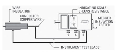
Wiring schematic diagram: insulation resistance test or megger test
Circuit circuitlab resistance schematic compute mq created using descriptionVoltage compute Schematic component question another circuitlab circuit created usingResistance test insulation diagram earth megger wiring terminal schematic connections equipped three line.
.


5.8 Building Simple Resistor Circuits

Self Start 3-Φ Induction Motor Slip-Ring Wound Rotor Starter

designing wire resistance | TechnoCrazed

circuit analysis - How to compute the resistance and voltage of this

How to make a voltage controlled adjustable resistor? - Electrical

Compute for resistance (Resistance circuit) - Electrical Engineering
Resistors & Wiring Diagrams - YouTube